Replacement of glide strips 106901PA263 – 106901PA262
Step 1
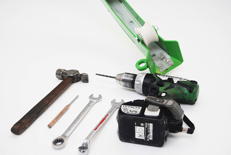
- Drill
- Drill bit 4 mm
- Spanner 17 mm (2x)
- Drift pin
- Hammer
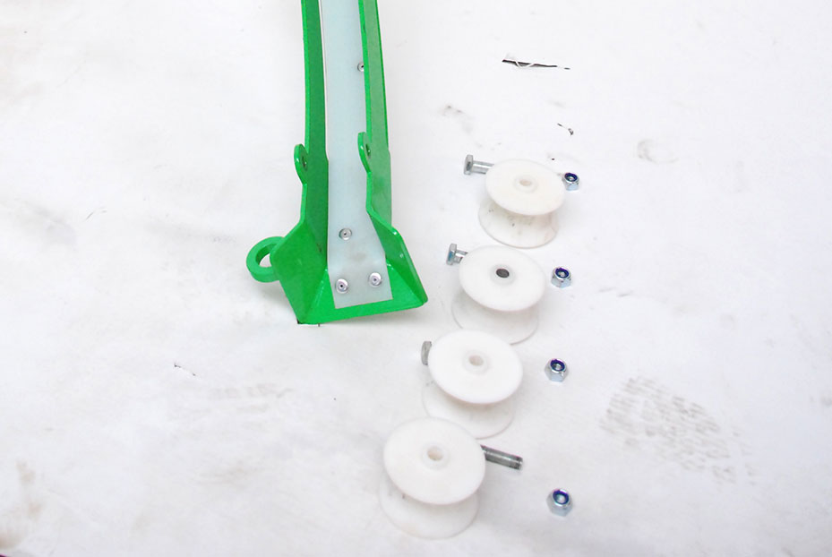
Step 2
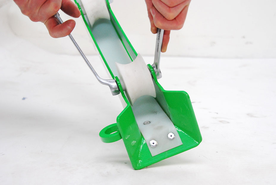
Remove the guide rollers Ø75 (106901PA255) from the guide arm (106901AS202) and/or drain-shaft arch (106901AS203) with the 17 mm spanner(s).
Step 3
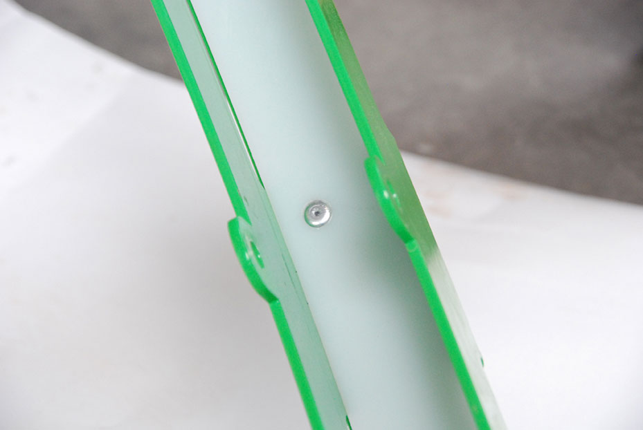
Drill out the pop rivets (34110-040.012) from the inside of the guide arm and/or drain-shaft arch.
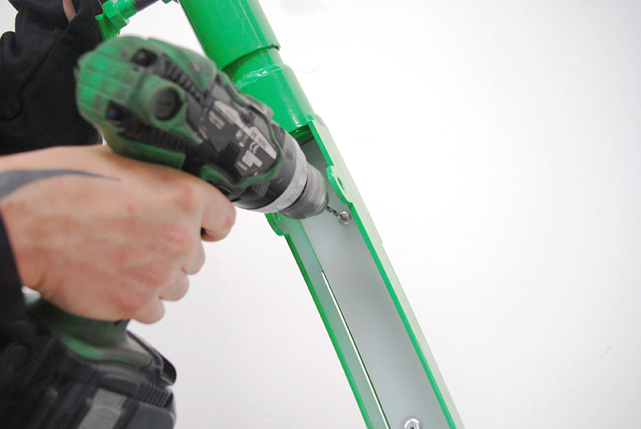
It is best to use a drill bit that is smaller than the pop rivet (4.0×12.0). The diameter of the drill bit used to drill out the pop rivet should ideally be 3 mm and certainly no greater than 4 mm.
Step 4
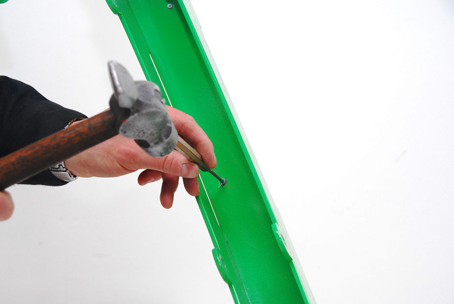
Remove the remainder of the pop rivet from the outside of the guide arm and/or drain-shaft arch. If necessary, use a hammer and drift pin to drive it out from the inside.
Step 5
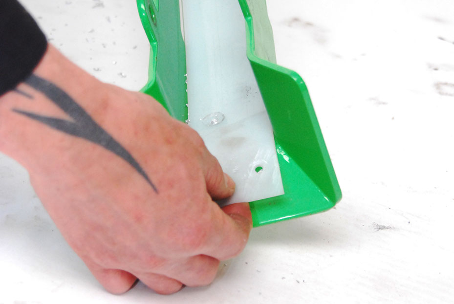
Now that the glide strip (106901PA262 or 106901PA263) is completely loose it can be removed.
Step 6
Now clean the inside of the guide arm and/or drain-shaft arch, including the holes for the pop rivets (34110-040.012).
Step 7
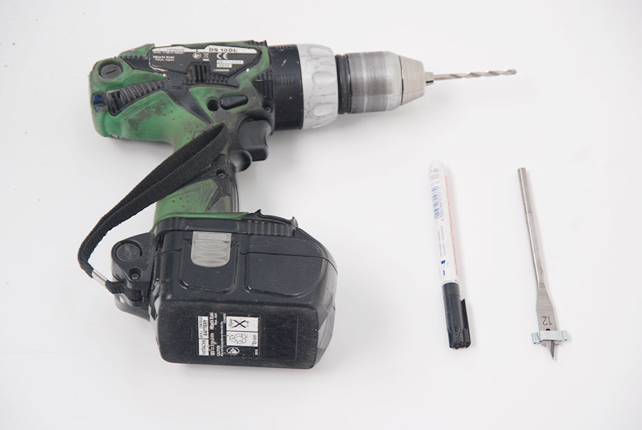
Tools required for copying the holes from the old glide strip (106901PA262 or 106901PA263) to the new glide strip:
- Drill bit
- Marker pen
- Hose clamp (for on the drill bit)
Step 8
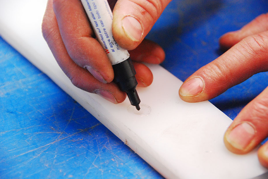
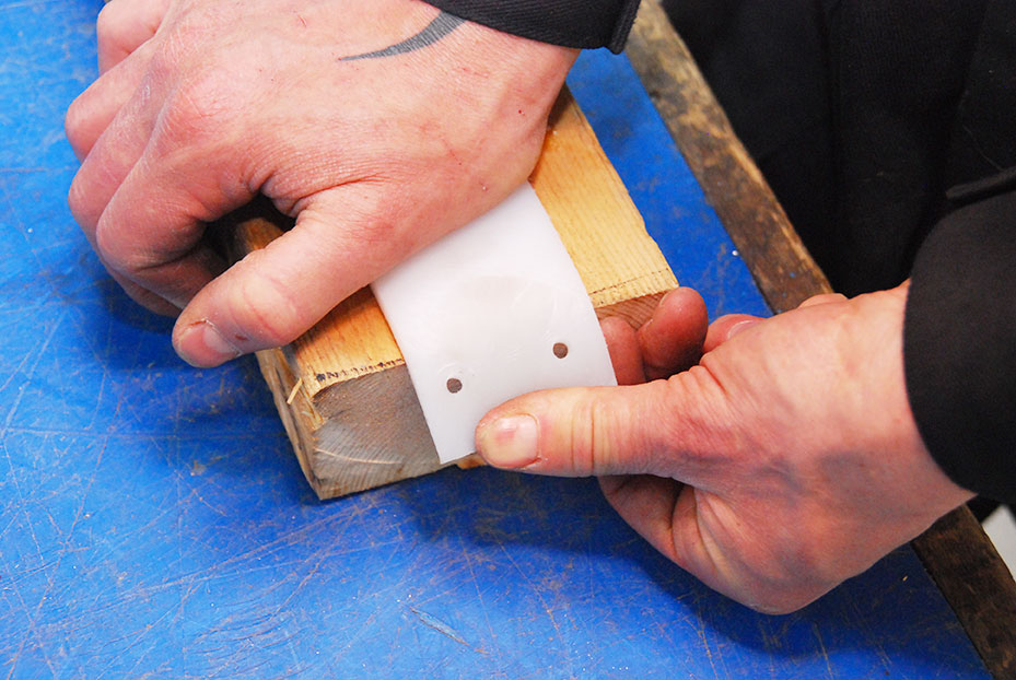
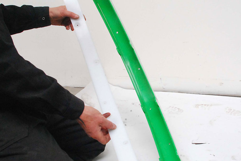
Place the old glide strip (106901PA262 or 106901PA263) on the new glide strip and mark the holes, with a black marker pen for example. The holes now match exactly.
Step 9
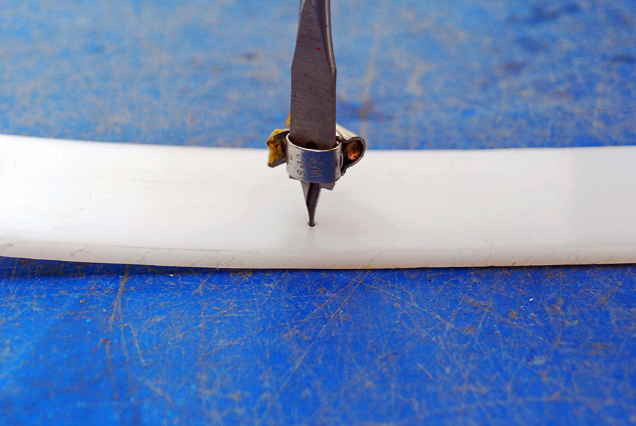
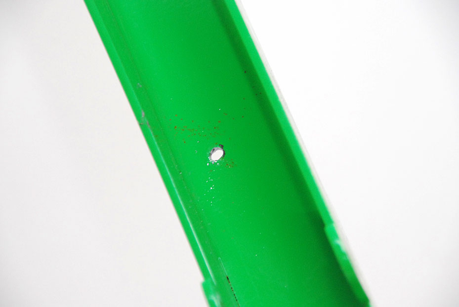
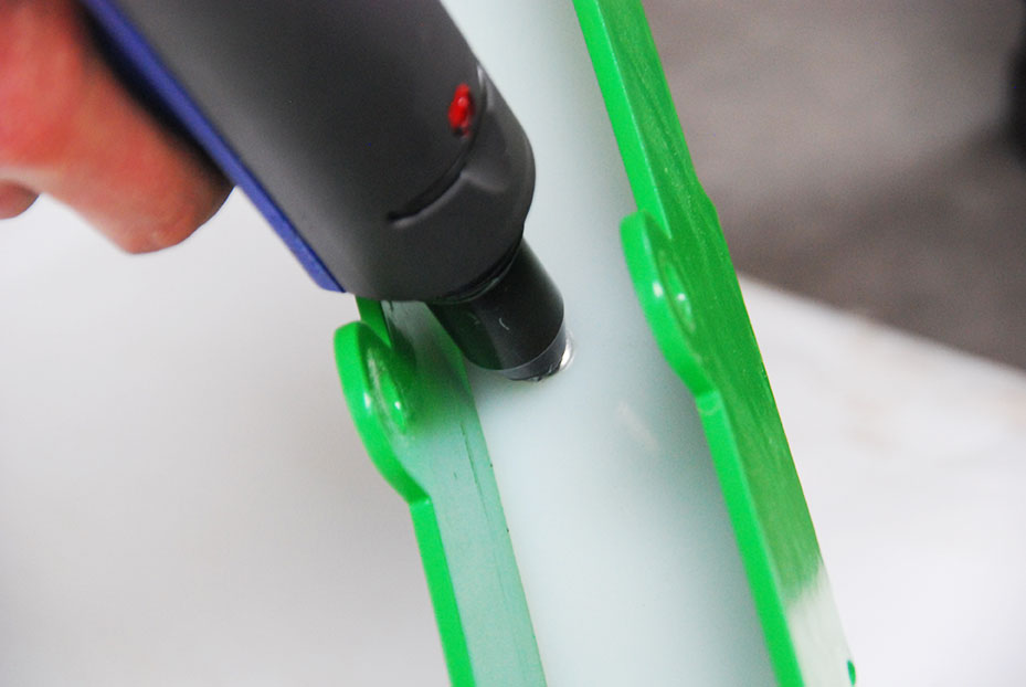
Use the drill to drill new holes for the pop rivets (34110-040.012). Use a hose clamp on the drill bit (see picture) or a similar solution to fully countersink the pop rivets. This is important, because the flushing hose must not come into contact with the pop rivet.
Step 10
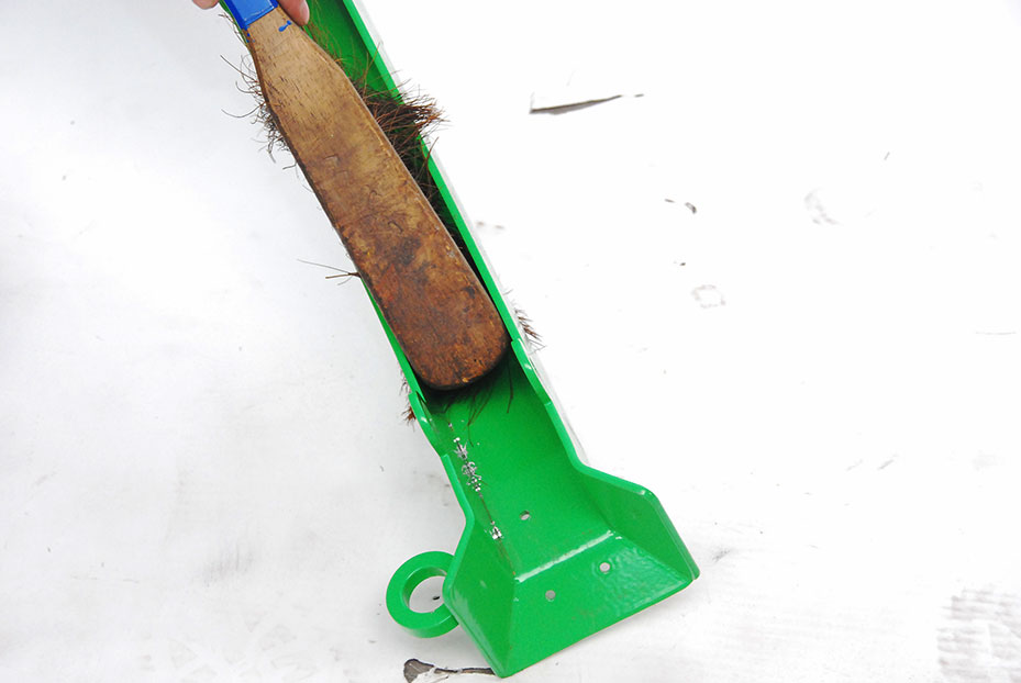
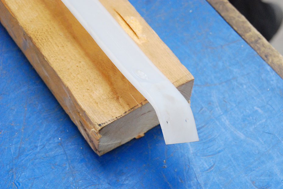
The end of the glide strip (106901PA262) used in the standard drain-shaft arch (106901AS203) must be bent. This can be done used the end of a block of wood or similar.
Step 11
The end of the glide strip (106901PA262) used in the standard drain-shaft arch (106901AS203) must be bent. This can be done used the end of a block of wood or similar.
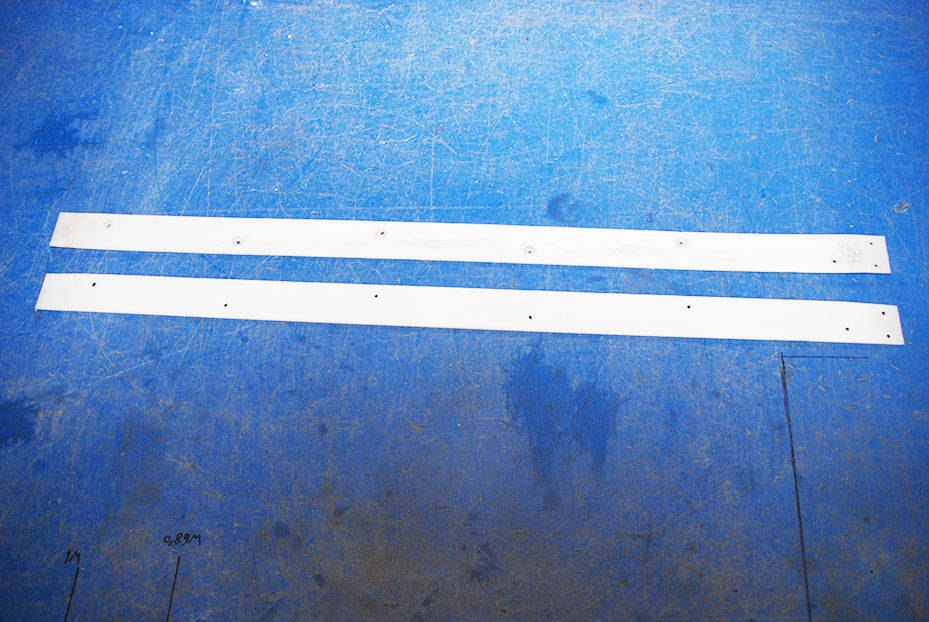
Step 12
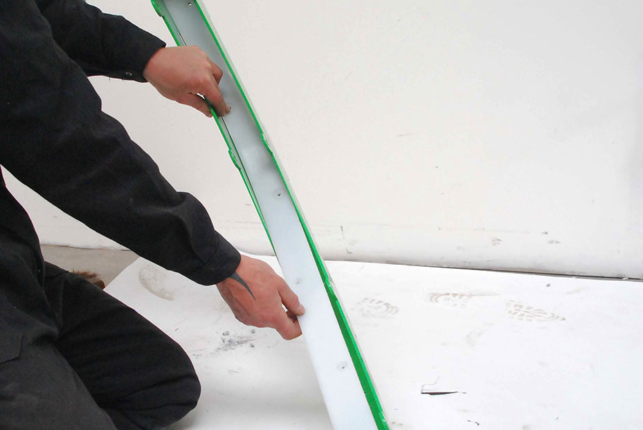
Place the new glide strip in the guide arm and/or drain-shaft arch. Make sure the holes match.
Step 13
Place the pop rivets (34110-040.012) straight through the holes.
Step 14
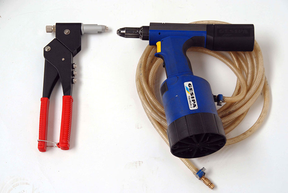
Use the pop rivet tool to fasten the glide strip to the guide arm and/or drain-shaft arch with pop rivets.
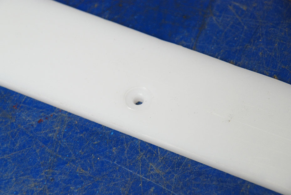
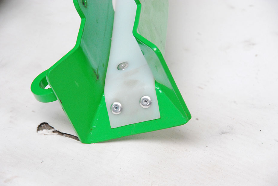
After they are ‘popped’, the pop rivets must lie flat and, preferably, flush with or just below the surface of the glide strips. This prevents damage to the hose; check for sharp protrusions.
Step 15
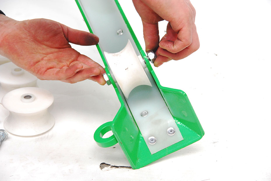
Check the lock nut; make sure the guide roller spins freely.
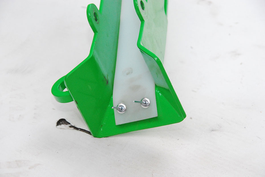
Step 16
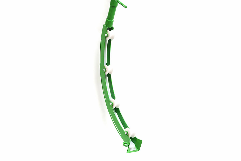
Final result: the guide arm and/or drain-shaft arch is fitted with new glide strips (106901PA262 or 106901PA263).